


Views: 0 Author: Site Editor Publish Time: 2026-08-28 Origin: Site


High-temperature calcination of battery anode materials requires strict contamination control and extreme thermal stability. Graphite containers endure punishing furnace environments to protect these sensitive materials from degradation. Process engineers must secure reliable tooling to guarantee high production yields. Off-the-shelf saggers often suffer from premature oxidation, thermal cracking, or poor stacking efficiency in specialized continuous or batch furnaces. They typically lack the geometric precision necessary for modern automated lines. Moreover, generic graphite can introduce unwanted impurities into delicate lithium-ion blends. Transitioning to custom-machined saggers requires exact engineering communication. This guide details the critical drawing specifications, acceptable tolerances, and QA documentation needed to evaluate and onboard a reliable manufacturing partner. You will learn exactly how to outline your dimensional requirements and material properties to prevent costly delays.
Design for Thermal Mass: Custom drawings must balance thin walls for thermal efficiency with sufficient thickness to prevent warping during repetitive thermal cycling.
Strict Purity Thresholds: Anode powder yields depend on ultra-low ash content; specifying ppm limits prevents unwanted elemental doping.
Dynamic Tolerances: Machining tolerances must account for the Coefficient of Thermal Expansion (CTE) at operating temperatures (typically 1000°C–3000°C).
Verifiable QA: A credible supplier provides raw material traceability, Coordinate Measuring Machine (CMM) reports, and documented oxidation treatments.
Battery material production demands exacting precision from every piece of equipment. Standard crucibles rarely meet the rigorous demands of modern anode manufacturing. They introduce operational inefficiencies and create significant product quality risks.
Chart 1: Standard vs. Custom Crucible Comparison
Feature | Standard Crucibles | Custom Machined Saggers |
|---|---|---|
Furnace Utilization | Low (Wasted internal volume) | High (Optimized footprint) |
Automation Compatibility | Poor (Frequent conveyor jams) | Excellent (Robotic grip optimization) |
Stacking Stability | Prone to lateral shifting | Secure interlocking lips |
Material Purity | Generic (Risk of ion leaching) | Ultra-high (Ash content controlled) |
Furnace Geometry Mismatch
Standard sizes leave unutilized space in pusher or roller hearth furnaces. This wasted volume drastically reduces daily throughput. It also drives up energy costs per kilogram of processed anode powder. Engineers must maximize the internal payload volume to maintain profitability. Furnace geometries directly dictate optimal sagger dimensions. A generic crucible simply cannot optimize the spatial constraints of specialized heating zones. Custom dimensions ensure optimal packing density.
Stacking and Automation Failures
Modern battery facilities rely heavily on robotics. Off-the-shelf options lack the precise interlocking features required for automated loading and unloading. They struggle to maintain stability during multi-tier stacking. Automated lines need specific grip points for robotic arms. Standard boxes often slip or jam on continuous conveyor systems. Custom designs incorporate custom lips and grooves. These features guarantee secure vertical alignment. If automated arms grip poorly designed boxes, production halts immediately.
Contamination Risks
Purity dictates final battery performance. Generic graphite often lacks necessary secondary purification. This oversight allows metal ions to leach into sensitive lithium-ion anode blends. Iron, vanadium, and sulfur impurities severely degrade battery capacity. Standard carbon blocks often contain residual ash. Extreme furnace temperatures vaporize these harmful impurities. The vapors then deposit directly onto the anode powder. You must avoid generic materials to protect your final product yields.
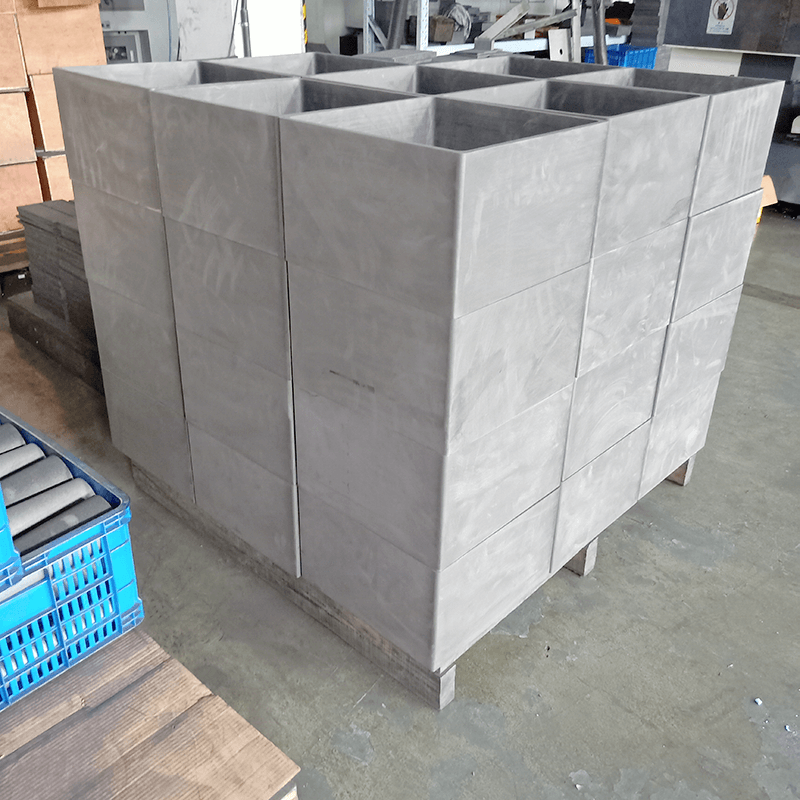
Engineering drawings form the exact foundation of successful procurement. Partnering with a reliable custom graphite sagger manufacturer requires clear and precise communication. You must detail every physical parameter to ensure functionality.
Process engineers face a delicate balancing act during design. You must specify wall dimensions carefully. Thin walls minimize thermal lag during intensive heating and cooling cycles. However, walls must retain structural integrity under heavy powder loads. Overly thick walls absorb too much radiant energy. This excess thermal mass wastes valuable furnace power.
You must also note specific assumptions regarding the anode powder. Record the specific gravity of the blend to calculate internal pressure at high temperatures. High-density powders exert significant outward pressure when heated. Specify a wall thickness capable of resisting these outward forces without bowing. A common mistake involves designing walls too thin for heavy synthetic graphite blends.
Continuous furnace vibrations can easily topple poorly stacked units. Detail tongue-and-groove or stepped-lip designs on your CAD drawing. These interlocking mechanisms ensure completely secure vertical stacking. A deep groove prevents dangerous lateral shifting during transit.
Additionally, consider your automated handling equipment. Specify appropriate draft angles on the exterior walls. Robotic handling arms require specific grip clearances to function properly. A typical draft angle of two to three degrees facilitates smooth equipment engagement. It also prevents mechanical grippers from binding painfully against the carbon surface.
Machined graphite is inherently brittle. Avoid sharp 90-degree internal corners entirely. Require specified radii to mitigate dangerous stress concentrations. Sharp internal angles act as inevitable fracture points. Thermal shock often initiates catastrophic cracks at these precise locations. A generous internal radius distributes thermal stress evenly across the structure.
Detail chamfered external edges on your digital files. Chamfers prevent chipping during manual or automated transit. Sharp external corners easily chip when loaded units bump against one another. These microscopic carbon chips can contaminate the delicate anode powder.
Material selection dictates long-term furnace longevity. Specifying a graphite sagger for anode materials involves much more than just physical dimensions. You must carefully dictate the physical and chemical properties of the carbon matrix.
Graphite structures expand as ambient temperatures rise. Establish tight dimensional tolerances (e.g., ±0.1mm) at standard room temperature. However, you must require the manufacturer to validate operating clearances. They must base these calculations on the Coefficient of Thermal Expansion (CTE). Evaluate this expansion at peak furnace temperatures.
Peak temperatures typically range from 1000°C to 3000°C. If you ignore CTE, interlocking lips will bind together. Stacks can jam dangerously inside continuous heating zones. A perfect slip fit at 20°C might become an inseparable weld at 2500°C. We strongly advise calculating expansion rates for all critical mating surfaces.
Follow these exact steps to manage dynamic tolerances:
Calculate baseline dimensions at standard room temperature.
Identify the peak operating temperature of your specific calcination process.
Apply the material's certified CTE multiplier to all mating features.
Adjust CAD drawing clearances to prevent high-temperature binding.
Density directly impacts long-term oxidation resistance. Specify bulk density minimums clearly on your purchase orders. We recommend targeting a bulk density greater than 1.85 g/cm³. Higher density limits the dangerous penetration of oxygen. It also blocks corrosive off-gases generated by the heated anode powder.
Highly porous carbon absorbs oxygen rapidly in reactive environments. This internal oxygen burns the carbon structure from the inside out. High-density blocks last significantly longer. They strongly resist structural degradation during repetitive thermal cycles.
Internal surface texture severely affects product yield. Dictate internal surface roughness (Ra values) explicitly on your prints. A smooth internal finish prevents anode powder from sticking to the side walls. It ensures clean discharge during automated unloading sequences.
Rough surfaces trap microscopic material particles. These trapped particles cause severe cross-batch contamination. They also require aggressive mechanical cleaning between uses. Aggressive cleaning accelerates internal wall wear. Specify a polished finish to minimize powder adhesion entirely.
Vetting potential partners protects your entire production line. A trusted high-purity graphite sagger supplier welcomes rigorous quality audits. Establish a strict evaluation protocol before awarding large manufacturing contracts.
Table 2: Supplier Quality Assurance Audit Matrix
Audit Category | Requirement Protocol | Acceptance Criteria |
|---|---|---|
Raw Material | Traceability documentation | Verified block origin (Isostatic/Molded) |
Chemical Purity | Certificate of Analysis (CoA) | Ash content <50 ppm or <5 ppm |
Dimensional Accuracy | CMM Inspection Report | 100% compliance on mating features |
Coating Integrity | Adhesion and thickness testing | No delamination under thermal shock |
Raw Material Traceability
Demand documentation proving the exact origin of the raw graphite block. You must verify the specific material grade used. Understand whether the material is extruded, molded, or isostatic. Isostatic blocks offer uniform multidirectional strength. This strength prevents catastrophic warping. Traceability ensures batch-to-batch consistency across multiple bulk orders.
Purity and Ash Content Verification
Impurities destroy overall battery efficiency. Require Certificates of Analysis (CoA) for every single shipment. These certificates must show ash content below specific limits. Standard applications tolerate less than 50 ppm. Ultra-high purity needs demand less than 5 ppm. We strongly recommend rejecting any batch lacking certified purity documents.
Dimensional Inspection (CMM)
Complex geometries require incredibly precise measurement. Ensure the supplier uses Coordinate Measuring Machine (CMM) testing. CMM reports rigorously validate first-article inspections. They verify complex shapes and stacking lip concentricity. A visual inspection cannot possibly confirm micro-tolerances. Insist on receiving raw CMM data for your first prototypes.
Anti-Oxidation Coating Validation
Many intense applications require protective surface layers. If specifying coated saggers, define the required coating thickness. Popular options include Silicon Carbide (SiC) or pyrolytic carbon coatings. You must define strict adhesion testing protocols. Poorly applied coatings peel off during the first heat cycle. This delamination contaminates the anode powder entirely.
Scaling up full production carries inherent financial risks. Implement a phased rollout to mitigate unforeseen mechanical failures. Real-world testing always reveals unexpected environmental variables.
The Pilot Batch Approach
Never order thousands of units blindly. Always mandate a small-scale pilot run before authorizing full production. We recommend testing 20 to 50 units initially. This pilot batch allows you to test thermal cycling in actual furnace conditions. Lab simulations rarely replicate the exact atmospheric nuances of an active production line.
Tracking Oxidation and Weight Loss
Graphite oxidizes and loses mass over prolonged time. Establish a baseline weight for the prototype saggers. Measure weight loss after 10, 20, and 50 cycles. This data allows you to accurately forecast operational lifespan. Tracking weight loss identifies premature degradation early. It helps process engineers optimize furnace atmospheres to reduce oxidation rates.
Handling and Storage Protocols
Storage conditions impact high-temperature thermal performance. High-purity graphite absorbs moisture from ambient air. Rapid heating in the furnace turns this moisture into pressurized steam. Expanding steam causes micro-fissures within the dense carbon matrix. Work with the supplier to define moisture-barrier packaging requirements. Vacuum-sealed bags with internal desiccants provide excellent protection. Keep units securely wrapped until immediately before use.
Specifying custom graphite saggers is an exercise in managing thermal dynamics, mechanical stress, and chemical purity. Off-the-shelf solutions simply cannot support the exacting standards of modern anode material calcination. Precision engineering and rigorous quality control remain paramount to operational success.
Consider these action-oriented next steps:
Finalize your 2D and 3D CAD drawings with clear dimensional tolerance callouts.
Define strict maximum ash content limits to prevent elemental doping.
Specify internal radii and external chamfers to mitigate mechanical and thermal stress.
Issue RFQs only to vetted manufacturers capable of providing transparent CMM and CoA documentation.
A: Generally, expect lead times of 4 to 8 weeks. This timeframe depends heavily on raw material availability, such as choosing between isostatic or molded blocks. Secondary purification processes also add time. CNC machining queues at the manufacturer dictate the final delivery schedule.
A: Lifespan is highly variable based on operating temperatures, furnace atmospheres, and physical handling. Inert atmospheres extend lifespan, while reactive environments accelerate oxidation. Engineers track longevity by monitoring cycle counts. They retire units once a predetermined weight-loss or dimensional degradation threshold is reached.
A: Not always. Isostatic graphite offers uniform multi-directional strength and a very fine grain structure. It handles extreme stress exceptionally well. However, high-quality molded graphite may suffice for static, lower-stress furnace environments. Molded options can offer significant cost efficiencies for less demanding applications.
A: Minimum order quantities vary widely by manufacturer. However, a prototype run of 10 to 50 pieces is a standard industry practice. This initial batch allows for thorough operational validation. Buyers typically validate these prototypes before committing to larger production runs of 500 or more units.

 +86-795-4605783
  sales@nhdcarbon.com
  No. 966 of Tiangong South Avenue, High-tech Industrial Park, Fengxin County, Yichun City, Jiangxi Province, China.


